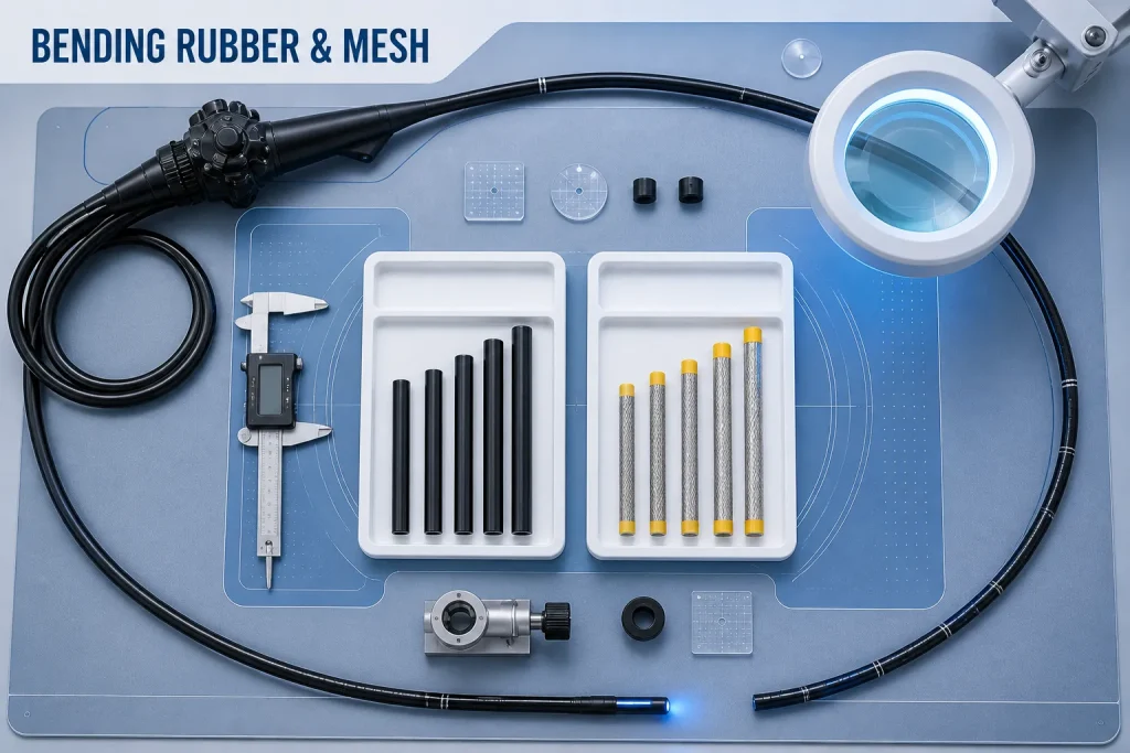
Bending rubber and bending mesh work together at the distal flexible section, but they perform different jobs and fail in different ways. The rubber provides the external flexible barrier, while the underlying mesh supports shape and load distribution around the articulated structure. During repair, judging only the outer sleeve can miss mesh distortion; judging only the mesh can miss sealing and surface problems that appear after assembly.
This article describes an engineer’s inspection sequence for a dismantled distal bending region. It does not provide model-specific assembly dimensions or replace the manufacturer’s service manual and IFU. Qualified personnel should perform the work using approved tooling, materials and acceptance criteria.
Document the Pre-Disassembly Condition
Before removing any covering, record leak-test status, visible cuts or swelling, maximum angulation, return to neutral and the location of abnormal stiffness. Photograph the distal region in neutral and in permitted articulated positions. Mark orientation using the approved method so later observations can be connected to a direction of movement.
A surface wrinkle at maximum angulation may be normal for one design and abnormal for another. Compare with controlled model documentation, not with memory or an unrelated endoscope.
What the Bending Rubber Can Reveal
Inspect under even light and magnification for pinholes, cuts, abrasion, chemical change, tackiness, permanent creases and separation at the attachment zones. Note whether damage is localized to a high-contact side or distributed around the circumference. A leak near an end bond may reflect installation, adhesion, surface preparation or underlying movement; it should not automatically be blamed on the rubber material.
Measure relaxed dimensions only by the approved method. Removed rubber may be stretched, swollen or distorted, so it is not a reliable master for ordering a replacement. Use the exact model and controlled dimensional reference when selecting from the bending rubber category.
Inspect the Mesh After Controlled Removal
Once the service procedure allows exposure, examine the bending mesh for broken wires, raised strands, local collapse, permanent twist, uneven diameter and movement relative to the underlying bending structure. Use magnification and rotate the assembly through the permitted view without applying unapproved bending force.
A raised strand can abrade or puncture a new rubber sleeve. A collapsed region can alter the final diameter or produce asymmetric bending. If mesh damage is found, replacing only the outer rubber may create a short-lived repair.
Record the Relationship Between Layers
- Orientation of the rubber defect relative to bending direction.
- Mesh condition beneath the same location.
- Diameter and roundness at defined reference positions.
- Condition of attachment and transition zones.
- Evidence of abrasion from a raised or displaced structure.
- Pre-repair angulation force and neutral return.
Check the Underlying Bending Structure
Mesh damage may be secondary to a distorted bending segment, abnormal wire load or impact. Inspect the articulated structure and cable path according to the model procedure. Confirm that movement is smooth before fitting new external layers. Do not use a new mesh or rubber sleeve to constrain an underlying structure that remains deformed.
Control Dimensions and Surface Preparation
Replacement selection should be based on specified diameter, length, material and model application. Soft components deform under caliper pressure, so use appropriate gauges or optical measurement when required. Prepare bonding and attachment surfaces exactly as specified; contamination, residual adhesive or sharp edges can compromise sealing and damage the new sleeve.
Condition flexible material in the approved environment before measurement and record the datum points, equipment and contact method. Check several circumferential positions when roundness matters. During trial positioning, avoid excessive stretching and never trim a replacement to compensate for an incorrect reference. If the specified sleeve, mesh and articulated assembly do not align within the documented process, stop and recheck identity, dimensions and underlying structure rather than forcing the layers together.
Verify the Completed Distal Assembly
After assembly and curing under the approved conditions, inspect surface uniformity, transitions and clearance. Exercise angulation through the prescribed sequence while watching for bunching, twisting, abnormal diameter change or delayed return. Complete leak testing and all required functional checks. Record the final maximum angulation and compare it with the pre-repair condition and acceptance criteria.
FAQ
Should bending mesh be replaced whenever bending rubber is replaced?
Not automatically. Inspect it against approved criteria. Replace or repair only when the evidence and model procedure support that action.
Can the old rubber determine the correct replacement diameter?
Not by itself. Service exposure and removal can change its dimensions. Use controlled specifications and verify the exact endoscope model.
Why can a new rubber sleeve leak soon after repair?
Possible factors include an uncorrected raised mesh strand, poor surface preparation, attachment-zone damage, incorrect dimensions or an underlying mechanical problem. Investigate rather than assuming one cause.
Conclusion
A reliable distal repair treats bending rubber, mesh and the articulated structure as one interacting system. Document the original symptom, inspect each layer, correct underlying damage and verify angulation and leakage after assembly. For compatible parts, contact Endopart with the model, controlled dimensions, inspection photographs and required quantity.