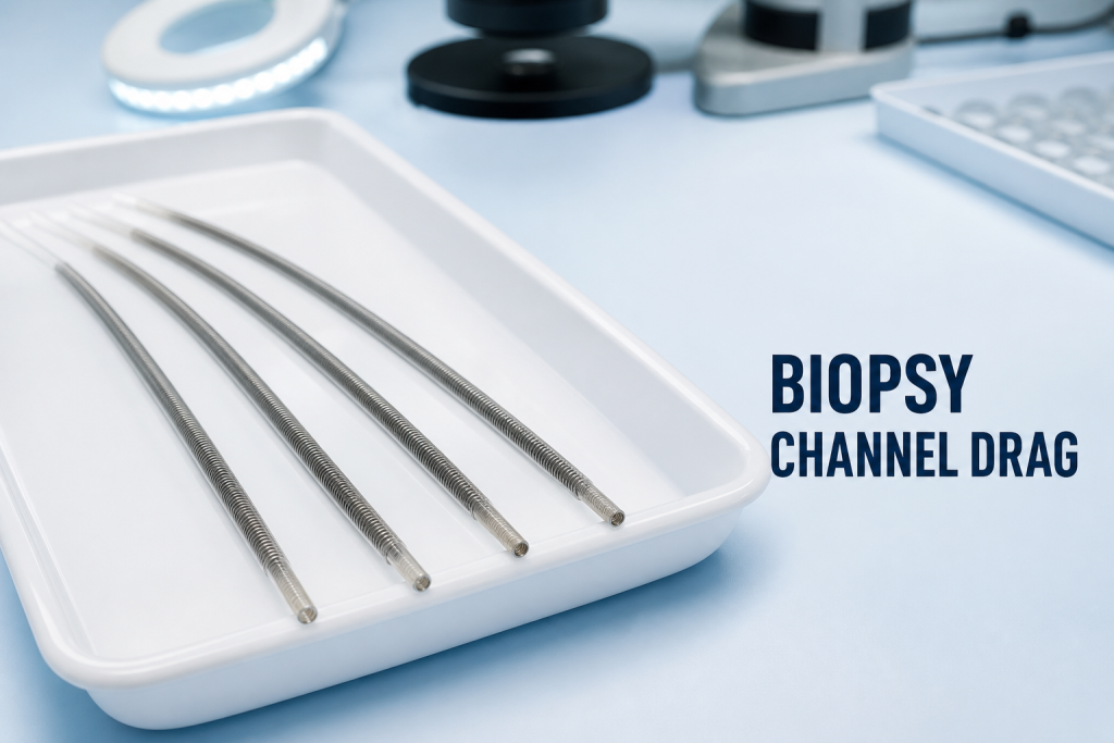
Instrument drag after a biopsy-channel replacement does not automatically mean that the new channel is too small. Resistance can originate from the test instrument, channel diameter, routing, a transition, excessive bend, adhesive intrusion or an adjacent structure. The location and conditions of drag must be reproduced before the repair is reopened.
This verification workflow is for qualified repair personnel using the exact manufacturer-approved tools and procedures. Follow the IFU, service documentation, cleaning requirements and post-repair acceptance criteria for the endoscope model.
Confirm the Test Instrument First
Use an approved, undamaged instrument or gauge of the specified size. Inspect its distal end, shaft and transitions for bends, burrs, coating damage or contamination. A worn test tool can create repeatable resistance in a correct channel and can damage a new lining.
Record insertion direction, endoscope position, angulation state and whether lubrication is permitted. Do not add unapproved lubricant to obtain a pass.
Locate the Resistance
Advance only with the force allowed by the procedure. Note the insertion distance where resistance begins, whether it is gradual or abrupt, and whether the tool can withdraw smoothly. Stop if force rises unexpectedly. Forcing passage can perforate or score the new channel.
Useful Comparison Conditions
- Neutral insertion section and neutral distal angulation.
- Each manufacturer-approved angulated position.
- Known-good test tool of the same controlled reference.
- Insertion from the permitted access direction.
- Repeat cycle count and exact point of resistance.
Check Channel Identity and Dimensions
Verify that the installed biopsy channel matches the exact model, controlled part reference, length and required inner and outer dimensions. Flexible tubing deforms under caliper pressure; use the specified measurement method and datums. A removed worn channel is not a reliable master.
Review Routing and Transition Zones
Compare the recorded installation route with model-specific documentation. Look for tight radius, twist, compression, excessive tension and interference at permitted inspection points. Inspect attachment and connector transitions for misalignment, adhesive intrusion or a sharp internal step. Do not infer routing from another model.
If resistance changes only during distal angulation, examine the bending-region path and length allowance. If it remains at the same insertion distance in neutral and angulated states, a fixed transition or local channel condition may be more relevant.
Relate Drag to Leak and Flow Tests
Instrument passage, leakage and suction flow assess different characteristics. A channel may pass a leak test yet have local drag, or pass an instrument while leaking at an attachment. Complete each required test independently and correlate the results rather than using one pass to imply overall conformity.
Correct the Supported Cause
Do not enlarge a channel with an improvised tool. If evidence shows incorrect identity, routing, transition assembly or material damage, follow the approved corrective procedure. Preserve photographs and the removed channel when supplier analysis is needed.
Inspect the Test Path Around the Control Body
Resistance near the proximal portion may involve the entry port, connector transition or routing through the control body. Inspect only the accessible regions authorized by the service procedure. Confirm that the channel is not twisted, pinched beneath a closure or pulled against a moving mechanism. Record the original routing before disturbing it.
A test tool that catches at the same insertion distance can help locate the region, but distance measured outside the endoscope is approximate unless the method defines a datum. Correlate it with drawings, external landmarks and controlled access rather than cutting into the channel to find the point.
Protect the Channel During Rework
Use specified fixtures and bend radii when repositioning tubing. Keep tools, adhesives and debris away from the lumen. If an attachment must be remade, follow required preparation, cure time and inspection steps. Do not use pressure or repeated tool passage to clear cured adhesive from a completed channel.
After rework, inspect the test instrument for new damage. A scored tool can transfer debris or damage the corrected channel during the next verification cycle.
Post-Repair Verification
Repeat instrument passage under the original neutral and angulated conditions. Confirm smooth insertion and withdrawal, required suction or flow performance, leak integrity and all related functions. Record the tool reference, insertion conditions, results and technician approval.
FAQ
Does drag at the distal bend prove the channel is too short?
No. Length allowance is one possibility, but routing, angulation geometry, transition condition and the test tool must also be checked.
Can a smaller tool be used to make the channel pass?
Only if that size is part of the approved test. A smaller instrument does not demonstrate compliance with the specified channel capacity.
Should the tool be forced past one tight point?
No. Unexpected force can damage the channel or tool. Stop, locate the resistance and inspect under the approved procedure.
Conclusion
Post-replacement instrument drag should be mapped to a distance and test condition, then traced through the tool, dimensions, routing, transitions and angulation path. For a compatible biopsy-channel inquiry, contact Endopart with the model, controlled dimensions, photographs and quantity.